- The principle of operation of the NRG system
- Installation of the system and analysis of the economic effect
- Product line
Download the brochure “Energy-saving system NRG”(2.5 Мb)
The latest Russian development in the field of energy saving and energy efficiency for any consumers of electric energy, such as private apartments, houses, shops, manufacturing sites, large industrial enterprises, etc.
The energy-saving NRG system is designed to reduce losses in the electrical network of any consumer of electricity, and therefore to reduce active power consumption and payments for electricity.
The main principle of the system is to saturate the consumer’s electrical network with additional free electrons, which increases the electrical conductivity and reduces the resistance of all conductors in the network. Consumer network means the entire electrical circuit located after the step-down transformer, which is a galvanic isolation that prevents the leakage of electrons into the external electrical network.
It is widely known that wear and tear of electrical networks means a complex of physical phenomena that adversely affect the electrical conductivity and resistance of all conductors in the network. But the main reason for the decrease in electrical conductivity and increase in the resistance of conductors in the network is the loss of conductivity electrons by conductors. In all places of the consumer’s electric network, where the temperature of the conductors reaches critical values (incandescent lamps, heating elements, etc.) or presence of sparking (relays, switches, etc.), there is an emission of electrons from the conductors into the surrounding space, which time leads to a decrease in the concentration of free electrons in the consumer’s network. To restore and increase the concentration of free electrons in the electric network, a constant source of free electrons is required, which must be connected to each phase and the zero wire of the alternating current electric network. Such a universal source is the energy-saving NRG system.
The system is based on four isolated units, which are connected to each phase and to the neutral wire of the consumer network after the step-down transformer. Each unit is filled with a special chemical compound, which has the following properties: while the units are in stock and are not connected to an alternating electric current network, no processes in the chemical compound take place, but as soon as the unit is connected to the alternating current phase through a copper cable, included in the compound, begin to react with each other.
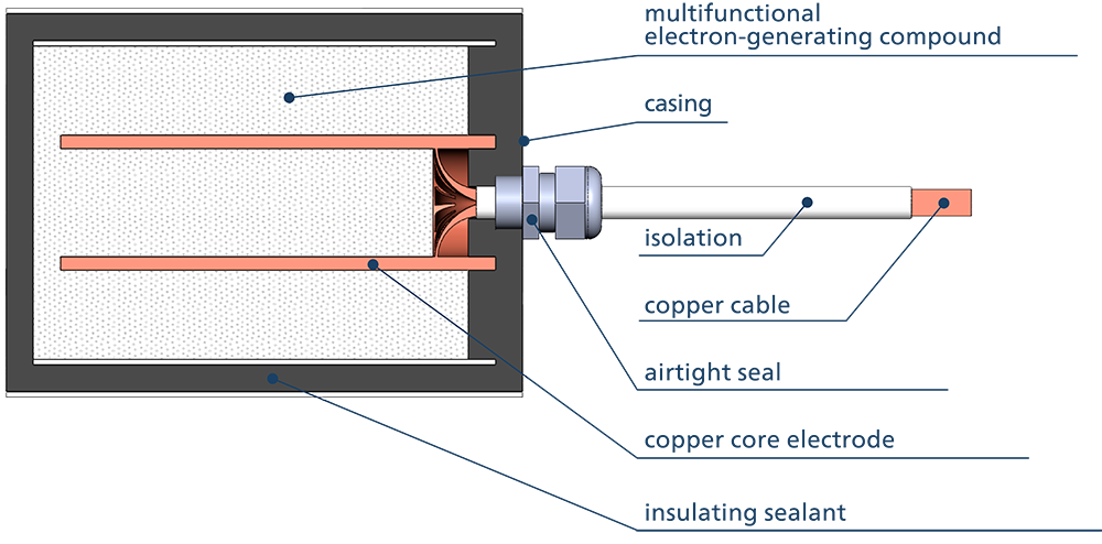
Fig. 1 NRG System Unit Internal Structure
An alternating electromagnetic field through a copper wire acts on the internal composition of each block and is the initiator of physicochemical processes between the substances that make up the compound. As a result of a chemical reaction, third substances are formed, and a large number of free electrons are released. Since each block is an electrically insulated vessel, the concentration of free electrons inside each block gradually increases and at some point becomes higher than the concentration of free electrons in the conductors of the consumer’s network, then free electrons begin to move from the zone with a higher concentration (NRG block) to a zone with a lower concentration (consumer network), which leads to an increase in the concentration of free electrons in the consumer network, to an increase in the conductivity of conductors and a decrease in the electrical resistance of all conductors in the consumer network.
Reduction of harmful harmonics
The peculiarity of this energy-saving system is that the electrons from the block enter the consumer’s electric network with pulses with a frequency that coincides with the frequency of the main harmonic in the network (in our case, it is 50 or 60 Hz), which leads to resonance and to superposition of the main harmonic with respect to harmful harmonics in the network (100, 150, 200, 250 Hz, etc.). Thus, harmful harmonics are suppressed and their amplitude decreases sharply.
Reactive power reduction
The voltage is primary in the electric network, in alternating current networks the voltage changes sign 50 times per second (at a frequency of 50 Hz), the direction changes smoothly - according to a sinusoidal law, on measuring instruments (oscilloscope) we see a voltage sinusoid. Following the voltage in the network, a current arises, which also changes and changes sign in a sinusoid, but in real networks the current sinusoid lags behind the voltage sine wave by some amount, during this period reactive power is formed, i.e. current has a sign opposite to voltage and does a negative job. This is because electrons have a certain inertia and mobility. Inertia is the property of an electron to resist an applied voltage. Mobility is the property of an electron to change direction following a change in voltage. Due to the heterogeneity of real conductors, the electrons in them have different inertia and mobility, but the higher the concentration of free electrons in the conductor, the greater the number of electrons that have high mobility, which helps to minimize the lag (delay) of electric AC current from voltage and thereby reduce reactive power in a particular network ceteris paribus.
System versatility
The system automatically tunes to the frequency of alternating electric voltage in the network and does not require any additional regulation and maintenance during operation. Based on the experience of using energy-saving systems at various facilities, we can conclude that this system is a universal device that can be used by any consumers of alternating electric current. But the best results in saving energy are achieved at facilities using electric networks of great length and branching, as well as where the main load is AC electric motors.
